

 [email protected] [email protected]
  +86 18986157930
  +86 18986157930
  [email protected]
 Wx279030189
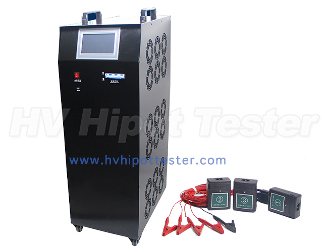
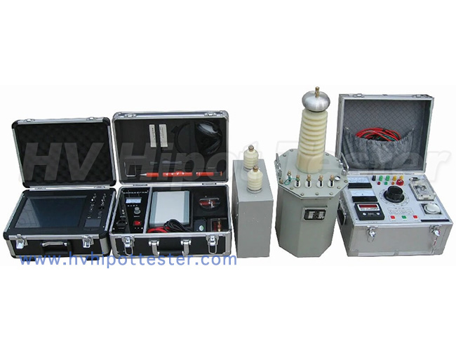
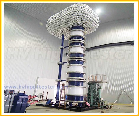
 High voltage withstand tester

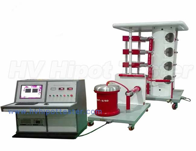
According to its function, it can be called electrical insulation strength tester, dielectric strength tester, etc. Its working principle is: apply a higher voltage than normal working voltage to the insulator of the device under test for a specified period of time, and the applied voltage will only produce a small leakage current, and the insulation is better. Program-controlled power supply module, signal acquisition and conditioning module and computer control system three modules form the test system. Select 2 indicators of the withstand voltage meter: the maximum output voltage value and the maximum alarm current value.
Comply with GB4706.1 standard, time, leakage current, AC and DC voltage are all digitally displayed, withstand voltage from 20kV to 100kV, leakage current from 0 to 200mA, time from 1s to 999s, users can choose according to product needs.
Single-chip control, high test accuracy, stable test performance, strong impact resistance, high voltage breakdown protection
Widely used in ultra-high withstand voltage test of household appliances, wires and cables, instruments and meters, the ultimate withstand voltage test of insulating materials, and the polarization of electro-acoustic equipment
Wait
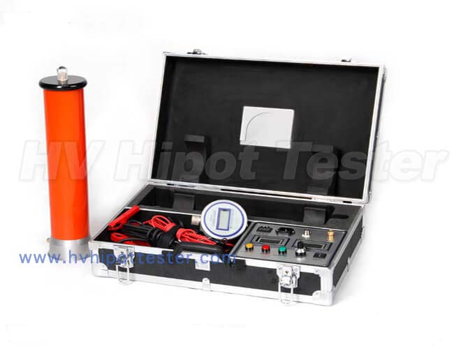
Withstand voltage tester, ultra high voltage withstand voltage tester, portable AC and DC high voltage withstand voltage tester, AC and DC ultra high voltage withstand voltage tester, AC and DC high voltage withstand voltage tester
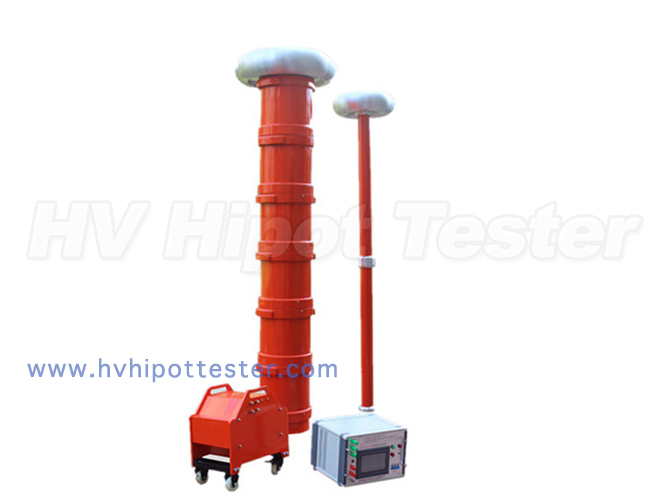
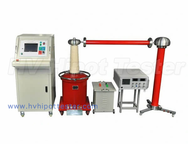
◇ Adopt the unique structure of axisymmetric unequal octagonal shell; it can output double high voltage.
◇ The oil level in the fuel tank is lower than the edge of the fuel tank to avoid oil leakage.
◇ The terminal is on the box cover to avoid collision and improve the mechanical and electrical performance.
◇ The product has the characteristics of compact structure, stable electrical performance, sufficient capacity, small size, light weight, convenient use and maintenance, etc.
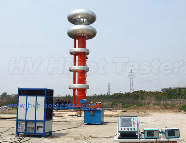
◆ Product type: AC, AC/DC, AC/DC cascade, AC/DC cascade.
◆ Input voltage: AC (0~200)V or (0~400)V.
◆ Output voltage: AC (0~200) KV or DC (0~280) KV.
◆ Capacity range: 0.5~200KVA.
◆Rated capacity: 1~400kVA;
The formula for determining the nominal test transformer capacity Pn: Pn=KVn2ωCt×10-9
Where: Pn----nominal test transformer capacity (kVA)
Vn-----The effective value of the rated output high voltage of the test transformer (kV)
K------Safety factor. K≥1, when the nominal voltage Vn≥1MV, K=2, when the nominal voltage is lower, the value of K can be higher.
Ct-----The capacitance of the tested product (PF)
ω----Angular frequency, ω=2πf, f----the frequency of the test power supply
The capacitance Ct of the equipment under test can be measured by an AC bridge. Ct varies greatly, depending on the type of equipment. Typical data are as follows:
Simple bridge or suspension insulator, dozens of microfarads
Simple grading casing 100 – 1000PF
Voltage transformer 200 – 500PF
Power transformer <1000kVA-1000PF
> 1000kVA 1000 – 10000PF
High voltage power cable and oil-impregnated paper insulation 250 – 300PF/m
Gas insulation-60PF/m
Enclosed substation, SF6 gas insulated 100 – 10000PF
For different test voltages Vn, choose different (appropriate) safety factors K. The K values selected for different Vn are listed above for reference
Vn = 50-100kV K=4
Vn = 150–300kV K=3
Vn> 300kV K=2
1. AC, AC and DC test transformer: Input the power frequency power into the operation box (or operation table), adjust the voltage through the auto-voltage regulator and input it to the primary winding of the test transformer. According to the principle of electromagnetic induction, power frequency high voltage can be obtained in the secondary (high voltage) winding. After the power frequency high voltage is rectified and filtered by the high voltage silicon stack, the DC high voltage can be obtained, and its amplitude is 1.4 times the effective value of the power frequency high voltage. It's just that the short-circuit bar should be drawn out when using DC, and the short-circuit bar should be inserted when using AC.
2. Test transformer with taps: In order to simultaneously satisfy the contradiction between a transformer with a higher voltage and a lower current and a higher current, the high-voltage winding is divided into two windings, one is the winding with the larger current and the other is The winding with the smaller current is then connected in series to draw out the two windings respectively. Principle diagram
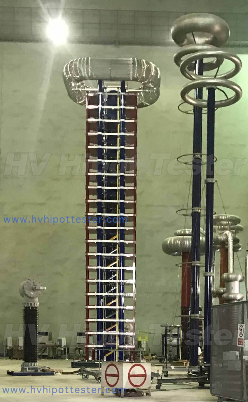
3. Cascade test transformer: In order to obtain a higher voltage test transformer, the cascade method can also be used to obtain a higher voltage. Figure 2 shows the principle wiring diagram of a three-stage cascade test transformer. The relationship between the capacity and voltage of the three transformers satisfies: P1=2P2=3P3, U (total)=1U+2U+3U.


[email protected]
[email protected]
+86 18986157930
[email protected]
Wx279030189